High-fidelity mesh on a co-axial rotor system
Coaxial rotor systems are appealing for multirotor drones, as they increase thrust without increasing the vehicle’s footprint. However, the thrust of a coaxial rotor system is reduced compared to having the rotors in line. It is of interest to increase the efficiency of coaxial systems, both to extend mission time and to enable new mission capabilities. This study investigates how adjusting the pitch of the lower rotor relative to that of the upper one impacts the overall efficiency of the system. A coaxial rotor system for a medium-sized drone with a rotor diameter of around 70 cm is used.
For the CFD analysis of this problem, the transient, incompressible Reynolds-averaged Navier-Stokes (RANS) equations and the k- shear stress transport (SST) turbulence model are used together. The simulations are performed using OpenFOAM. The Arbitrary Mesh Interface (AMI) method in OpenFOAM is used for the handling of the rotating blades.
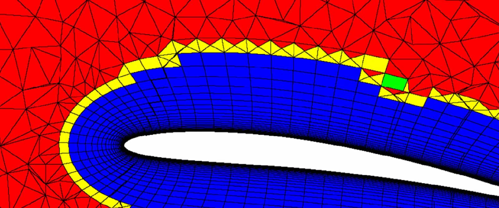
Pointwise is used for the mesh generation of this case. Following its “bottom-up” meshing approach, the first thing to focus on is the surface mesh of the rotors. Given the stronger surface curvature, the leading edge and trailing edge typically need a finer mesh, while moving down the wing chord a coarser mesh is possible. The wing taper ratio and geometric twist make it more difficult to build a smooth and homogenous surfa mesh. The 2D T-Rex algorithm of Pointwise is perfect to address this challenge. As shown in Figure 1a, T-Rex allows us to grow layers of rectangular cells given the first cell thickness and a growth factor, and the inflation is stopped once a smooth dimensional transition with the rest of the surface mesh is achieved. The rest of the upper and lower surface domains consist of triangles and quads generated by the “advancing front ortho” algorithm and are automatically shaped to comply with high-quality criteria, whilst fulfilling a specified maximum cell dimension.
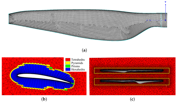
Figure 1. Illustration of mesh arrangements. (a) Rotor surface mesh. (b) Close-up of mesh near rotor with layers generated using 3D T-Rex extrusion. (c) Mesh around rotors. The yellow rectangles indicate the AMI blocks.
As shown in Figure 1b, once a reasonably fine and high-quality 2D grid is obtained, the 3D T-Rex algorithm is employed to inflate layers of high-aspect-ratio hexahedra and prisms in the near-wall region to effectively capture viscous effects. Then the mesh will transit into pyramids and finally into tetrahedra, which fill the remaining AMI blocks as indicated by the yellow rectangles in Figure 1c. The remainder of the far-field domain surrounding the AMI blocks is cylindrical and fully consists of isotropic tetrahedra with increased characteristic dimensions.
OpenFOAM is very sensitive to cell non-orthogonality, which is defined as the angle between a line connecting the centroids of the two cells and the normal of the shared face. Generally, it is required that the majority of the cells should have a cell non-orthogonality below 75 to ensure the convergence of the simulation. Pointwise has this cell quality criterion implemented in the “examine” panel which allows the user to monitor this cell property directly within the software. For this case, a reasonable trade-off between cost efficiency and cell quality has been found, with the number of severely non-orthogonal cells (>70) reduced to less than 600 per AMI block and grouped in non-critical flow regions. The simulations have shown that a stable solution is achieved successfully with this setup.
The wall y+ value is an important mesh design parameter to allow an accurate flow resolution in the near-wall region. For the numerical solver employed in this study, which does not implement any wall function, it is preferable to have y+≤1 so that the first cell center is placed in the viscous sublayer. As shown in Figure 2, the y+ value is lower than 1 over most of the rotor surface, except in a small region at the leading edge. It is overall lower than 2 across the entire blade, thus indicating a satisfactory resolution for the viscous effects.
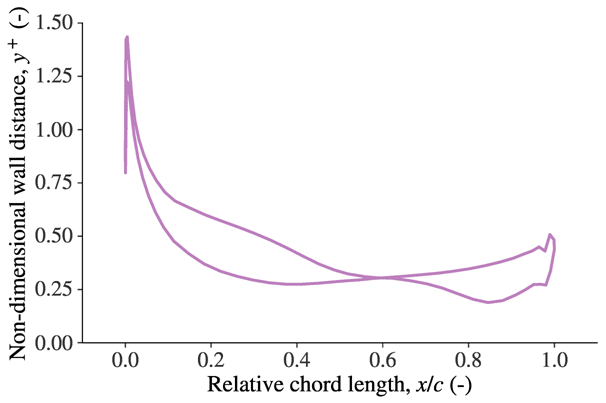
Figure 2. Non-dimensional wall distance along rotor surface at radius r = 0.7R for RPM = 2200.
The numerical results have been validated with experimental results. The experiment is performed on a high-precision dynamometer and a thrust stand, and the angular speed is measured with an optical tachometer. Previous attempts performed within the University of Stavanger have shown that CFD simulations over meshes designed with OpenFOAM’s snappyHexMesh tool did not achieve a reasonable matching with experimental results. For the mesh designed with Pointwise, on the other hand, the CFD results show a very good agreement with the experimental results for both the single and coaxial rotor cases. It can be concluded that the power of Pointwise algorithms and customization features played a significant role in the success of the simulation campaign.
Project background
The project has been performed as part of a collaboration between neptech AB and the University of Stavanger, Department of Mechanical and Structural Engineering and Materials Science. Neptech is Pointwise sales partner in the European Nordic countries. The project has been led by Dr. Knut Erik Teigen Giljarhus, associate professor at UiS, and is published open access in “MDPI Drones” journal at the following link: https://www.mdpi.com/2504-446X/6/4/91.
References
- Giljarhus, Knut Erik Teigen, Alessandro Porcarelli, and Jørgen Apeland. “Investigation of Rotor Efficiency with Varying Rotor Pitch Angle for a Coaxial Drone.” Drones 6.4 (2022): 91.
Category
Drones
Application
Aerospace - Multirotor drones
Date
April 2022
Project Partner
UiS - Knut Erik Giljarhus
Pointwise Key Features
3D TRex and multiblock mesh