How to Mesh a Frozen Drone
How to Mesh a Frozen Drone
Richard Hann, Norwegian University of Science and Technology (NTNU)
Icing of drones is a severe hazard that significantly limits the usage of autonomous unmanned aerial vehicles (UAVs). Computational fluid dynamic (CFD) methods, originally developed for manned aircraft icing, are an important tool for understanding the effects of icing on UAVs. One of the most challenging tasks for the simulation is the generation of high-quality meshes of complex ice shapes.
Atmospheric icing, also called in-cloud icing, occurs when an aircraft encounters supercooled droplets in the atmosphere. Liquid droplets, with a temperature below freezing, turn into ice when they collide with the airframe. Small surfaces, like wings, elevators, and propellers are particularly sensitive to icing and can accumulate significant amounts of ice on the leading-edge. The resulting ice shapes are disrupting the airflow and lead to a decrease in aerodynamic performance. The typical penalties are an increase in drag, a decrease in lift, and a reduction of the stall margin. Atmospheric icing is, therefore, a severe hazard to all aircraft and have catastrophic consequences.
Wind tunnel experiments on UAV icing by NTNU and UBIQ Aerospace at the icing wind tunnel facilities at VTT.
UAVs are an emerging technology with many potential applications. Some that are particularly relevant when it comes to icing are operations that are occurring beyond visual line of sight (BVLOS), because icing can occur without the ground pilot noticing. BVLOS mission are required for many of the drone application which are currently discussed, e.g. package deliveries, search & rescue, communications, or pipeline monitoring. Management of the icing risk is a key step in ensuring that these applications can be conducted safely and reliably in the future.
Until today, very little research has been conducted on the differences between icing on manned and unmanned aircraft. One of the things we are working on is to understand how icing affects the aerodynamic performance of a fixed-wing UAV. Numerical icing codes, mostly developed for manned aircraft applications (e.g. LEWICE, FENSAP-ICE), are a useful tool to investigate icing on drones. These icing codes typically rely on CFD methods to simulate the flow field and to calculate the impingement rates of droplets on the airframe. We use these codes to simulate ice shapes and to compare the clean and iced aerodynamic performance on 2D and 3D UAV geometries. To validate the numerical results, we have conducted several experimental campaigns in specialized icing wind tunnels that are able to generate icing conditions under laboratory conditions.
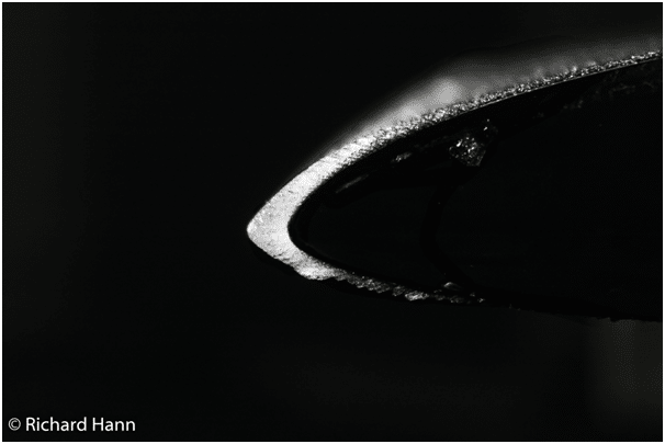
Figure 1 – Experimental rime ice shape
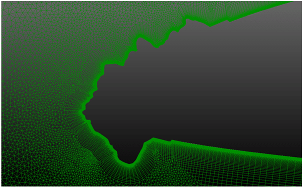
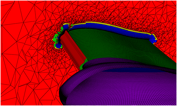
A key input for all CFD tools is a good mesh. The ice horns that form on the leading-edges of wings are particularly difficult to discretize. These ice shapes are characterized by irregular and complex geometries that need to be meshed well in order to accurately capture the aerodynamic penalties. We are using Pointwise to generate hybrid T-Rex meshes, with a structured grid in the boundary layer and an unstructured grid in the far-field. The T-Rex functionality is able to capture the complex ice structures reliably and requiring little manual adjustments. Since we are dealing with large numbers of ice shapes, we are also relying on the macro-function of Pointwise to automate our workflow. We use the resulting meshes in combination with ANSYS FENSAP-ICE on 2D and 3D UAV geometries to simulate the aerodynamic penalties at low Reynolds numbers (ca. 1,000,000).
Figure 2 – Hybrid T-Rex 2D mesh on a complex experimental glaze ice shape.
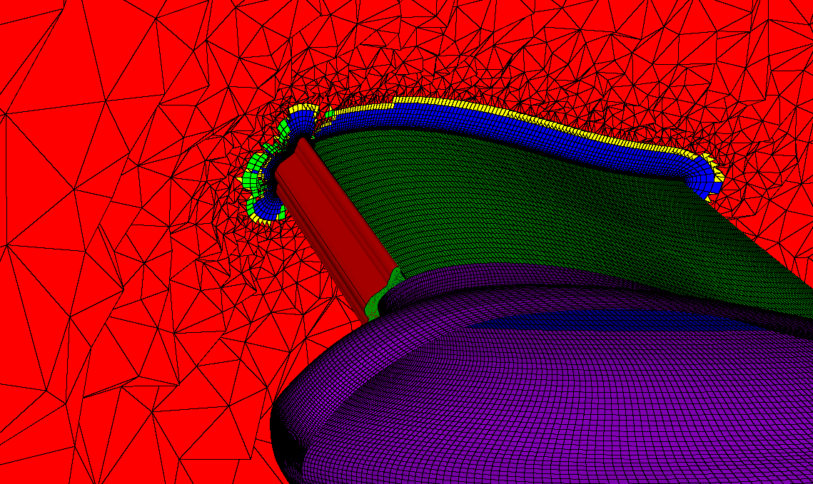
Figure 3 – Hybrid T-Rex 3D mesh on a full-scale UAV with artificial ice shapes attached to the wing.
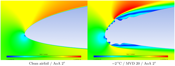
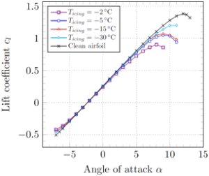
The CFD results show that the degree of performance degradation is strongly related to the temperature. The reason for this is that the temperature governs the ice shape. At very low temperatures all incoming droplets freeze upon impact, forming relatively streamlined rime ice shapes. At temperatures close to freezing, only a fraction of the droplets freezes immediately. This can lead to complex glaze ice horns that are associated with large penalties.
Figure 4 – Example of CFD results for a clean and iced airfoil (source: Fajt et al, 2019)
Figure 5 – Simulation results for the aerodynamic performance degradation at Re=800,000 (source: Fajt et al, 2019)
We are currently working on the validation of the numerical tools with experimental data and aim to publish more information next year. In the future, our objective will be the numeric simulation of iced UAV propellers and rotors, which will be also very challenging when it comes to meshing.
Further references:
- Hann, R. (2019). UAV Icing: Ice Accretion Experiments and Validation. SAE Technical Paper. No. 2019-01-2037. DOI: 10.4271/2019-01-2037
- Fajt, N., Hann, R. (2019) The Influence of Meteorological Conditions on the Icing Performance Penalties on a UAV Airfoil. 8th European Conference for Aeronautics and Aerospace Sciences (EUCASS). DOI: 10.13009/EUCASS2019-240


