Mesh morphing of an airfoil with foldable Krueger flap
Krueger flap is a famous kind of lifting enhancement device fitted onto the leading edge of the wings. The flap remains retracted during the cruise and is hidden inside the main wing. During take-off and landing, it will be deployed by rotating around a hinge at the leading edge of the main wing to increase the wing camber and get a higher maximum lift coefficient. In this case study, as part of the UHURA H2020 project (https://uhura-project.eu, https://cordis.europa.eu/project/id/769088) coordinated by DLR, the simulation of the deployment process of a foldable Krueger flap is presented. The process of the deployment of the flap is shown in Figure 1.
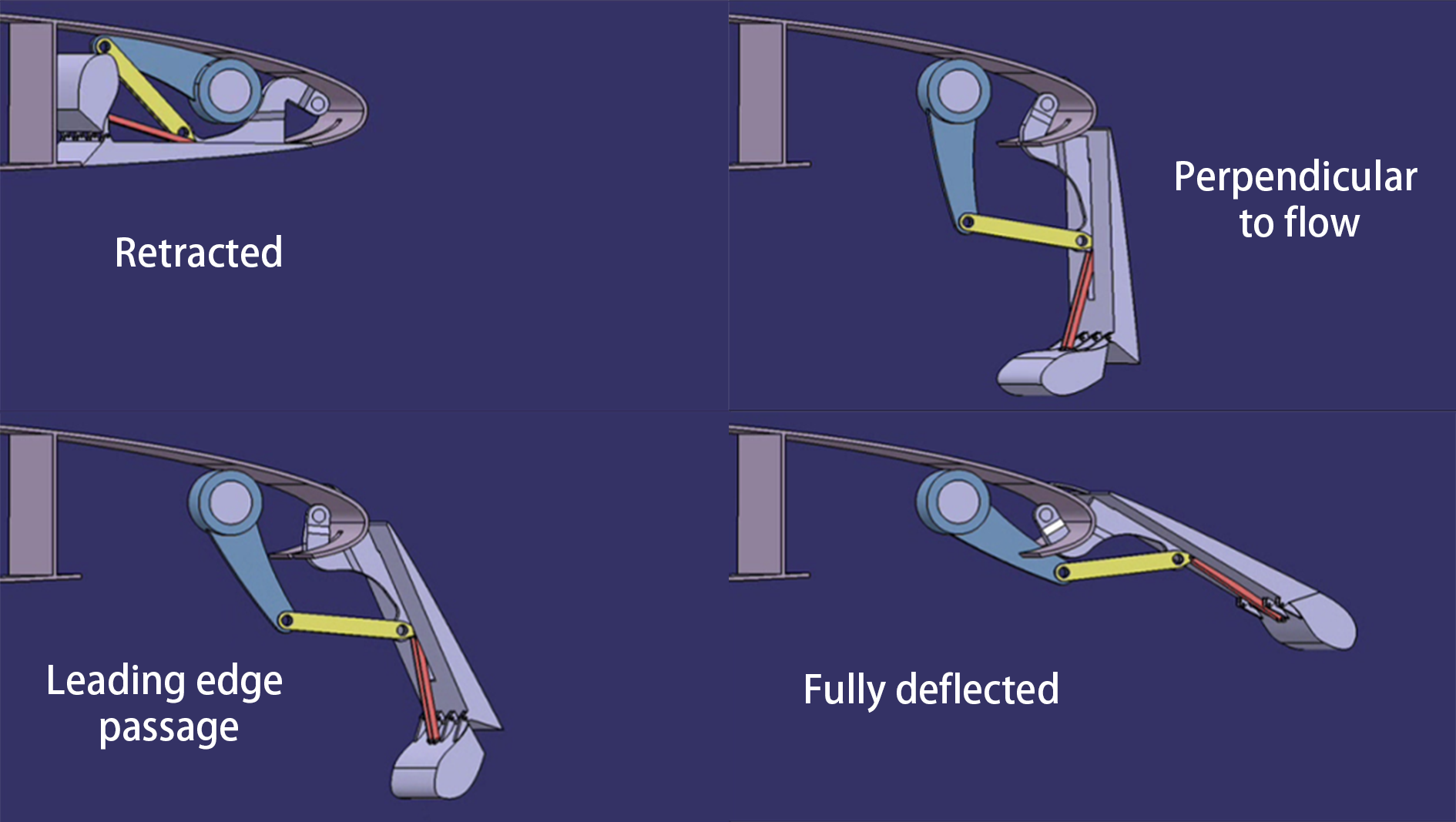
Figure 1: Deployment of the Krueger flap.
To simulate this deployment process in CFD, the mesh morphing technique is required to adapt the mesh according to the position of the Krueger flap. Mesh morphing is a way to adapt the mesh to the model that will change shape during the simulation. Only the x, y, and z coordinates of the nodes will change during mesh morphing. Hence, the topology of the mesh, including nodes count, cell count, and connectivity, is maintained. Hence, the amplitude of the morphing is restricted for maintaining good mesh quality before remeshing and interpolation is necessary. For this case, Pointwise scripting language (Glyph2) is used for the mesh automation process. A Glyph script is used to generate different mesh files with different deployment angles of the surfaces. The angles are read from a file where they are tabulated. After that, the solver will be provided the mesh files at sufficiently close deployment angles and perform the morphing across the unsteady simulation.
The high lifting device is composed of two surfaces, one is the Krueger panel connected with the main wing by the hinge and the other is a foldable bullnose. Hence, each deployment position of the flap is defined by a set of two angles, one per surface, and the deployment will be then defined by a sequence of the two angles. The combination of these 2 angles is fixed for a given moment during the extension.
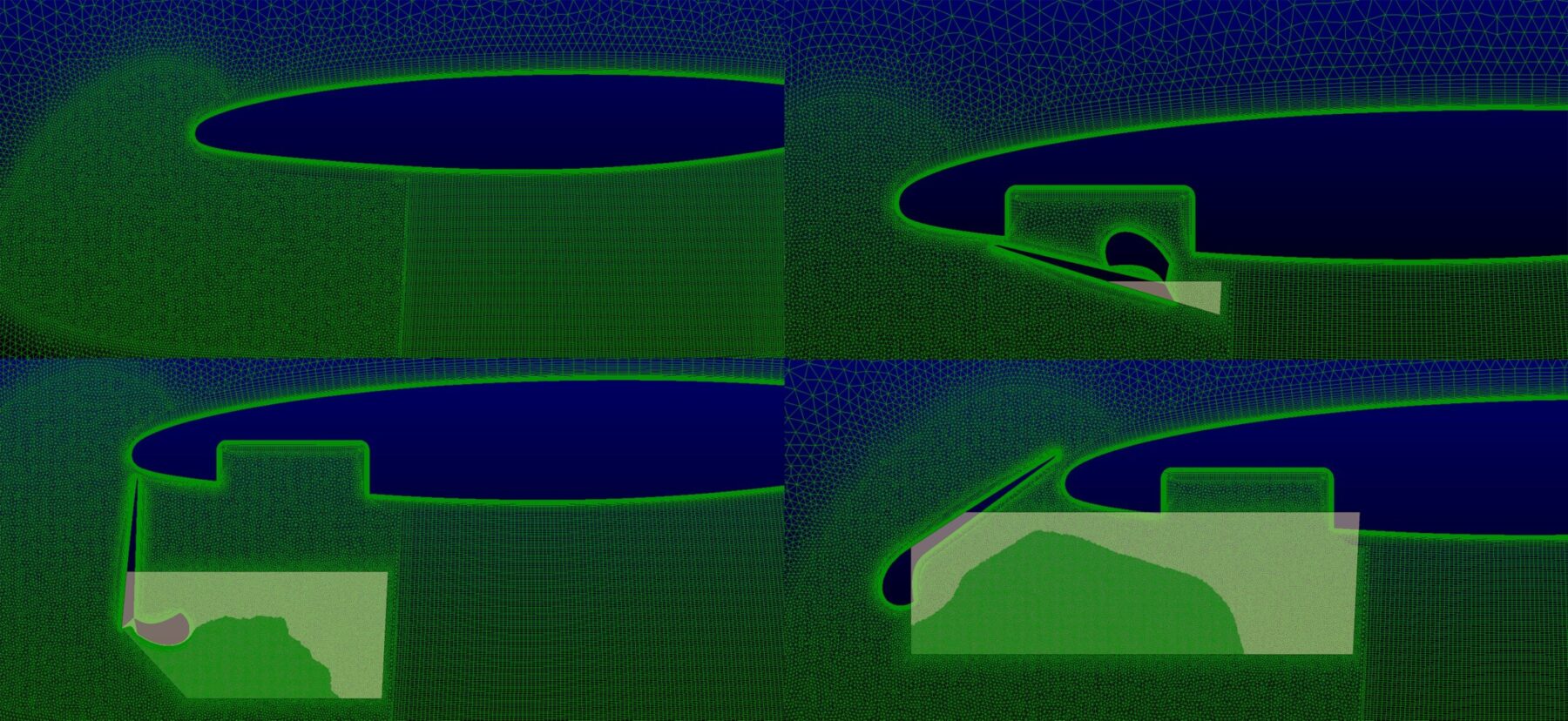
Figure 2: high lifting surface deployment process. The mesh downstream of the flap is refined locally according to the deflection angle.
The flap is initially hidden under the main wing and forms a water-tight structure. In this condition, the flap is invisible in the mesh. As the flap deploys gradually, the mesh changes accordingly (Figure 2). It should be noted that only the mesh in the domain where the flap moves changes. The reminder of the mesh will remain unchanged, which can shorten the time for the mesh morphing process.
For the turbulent models used in this study, as well known by the insiders, CFD always consists of a trade-off between accuracy and computational time. Hybrid RANS-LES computations can be a possible solution in cases requiring a precise turbulent flow resolution only in particularly limited domain regions. The idea behind Large Eddy Simulations (LES) consists of modelling the statistical influence of the smallest turbulent length scales onto larger length scales and of simulating only the latter. To achieve this goal, a modern practical approach suggests considering the large-scale field as the field obtained by the application of a filter to the real field. In the regions where LES is performed, the width of the filter is related to the grid spacing.
For this case, in order to save computational time, RANS are used in most of the domain where the flow is attached. LES will be introduced by the algorithm when the turbulence length scale exceeds the grid resolution. In the domain investigated, a separated and highly turbulent flow is expected downstream of the flap during its deployment process. Hence, in this region the turbulence length scale threshold level will be certainly exceeded. To get a finer mesh behind the flap such that it fulfils the LES requirements, the area is enclosed by a polygonal mesh source. The source is programmed in the script to reshape according to the flap position. As it can be observed in the mesh in Figure 2, the points defining the polygonal source are adjusted at every deployment angle such that the region downstream of the flap is always sufficiently refined to perform LES simulations. Downstream of the dynamic zone, a uniform hexahedral mesh zone is introduced to capture the resolved turbulence with good efficiency in terms of accuracy v.s. computational cost. Figure 3 shows an example:
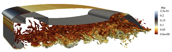
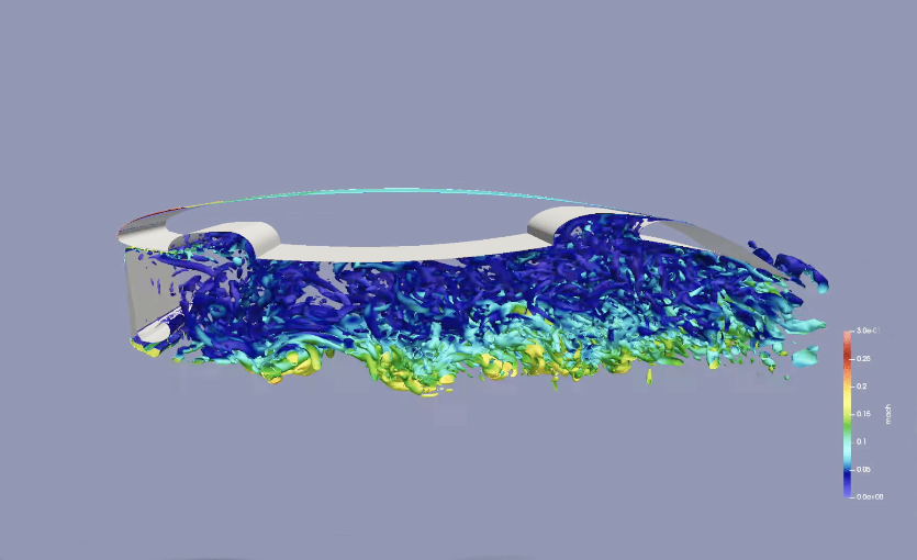
Figure 3. Resolved turbulence visualized during the deployment process. Hybrid RANS-LES computations at KTH utilising the mesh in figure 2.
This case study provides an example of the versatility of Pointwise when it comes to mesh automation. Running a single script allowed to generate a set of many mesh files directly importable to the CFD solver and ready to be mesh-morphed and simulated. This automation process has not been traded with any mesh detail and local feature. In fact, it is shown that every mesh file generated has adapted features according to the given geometrical setup, so that high-quality simulation results are always ensured.
Chen, S., Bagheri, F., Eliasson, P. & Wallin, S. Hybrid RANS-LES simulation of a deflecting Krüger device. Presented at 10th EASN International Conference, 2020.
Acknowledgments
The project leading to this article has received funding from the European Union’s Horizon 2020 research and innovation programme under grant agreement No 769088.
Category
Aerospace
Application
Deploying High Lift devices
Date
August 2022
Project Partner
KTH - Uhura EU project
Pointwise Key Features
Scripted dynamic local mesh refinement for unsteady LES applications