Meshing and CFD Simulations of High-Lift Devices Design in a Turboprop Aircraft
As an environmentally friendly means of transport, turboprop aircraft can save fuel up to 20% compared with turbofan aircraft. However, some traditional high-lift devices such as slotted leading edge flaps will not be suitable for turboprop engines due to the smoothness requirement at the upper surface. Therefore, a flexible leading edge design that can be drooped during take off and landing is introduced. The CFD analysis in this project is presented to study the effect of morphing devices for the drooped wing leading edge, geometry morphed flaps and winglets. The study was performed within the project WTM-RECYCLE, which received funding from the Clean Sky 2 Joint Undertaking under the European Union’s Horizon 2020 research and innovation program under grant agreement No 755605.
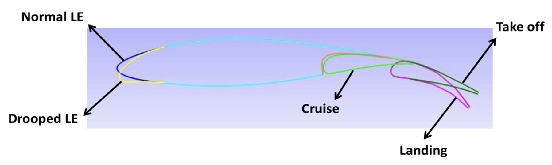
Figure 1 – The different configurations used for the CFD study are shown as profiles through the inboard wing section.
Figure 1 shows the different wing shapes in different flight situations. The leading edge is drooped during both take off and landing. The surface mesh of the 3D model is mostly structured. However, there are some sharp corners when the leading edge is deployed in the connection area with the trailing edge, as shown in Figure 3. The T-Rex algorithm of Pointwise is employed here to ensure a smooth cell area ratio and volume ratio at these corners. The structured mesh and quad-dominant mesh have thus a smooth transition even in the proximity of sharp corners.
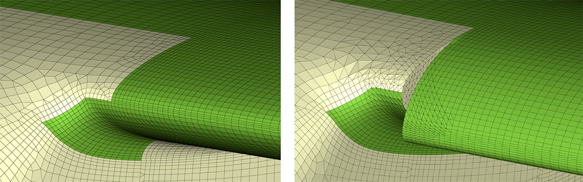 Figure 2 – Surface mesh of normal (left) and drooped (right) leading edges.
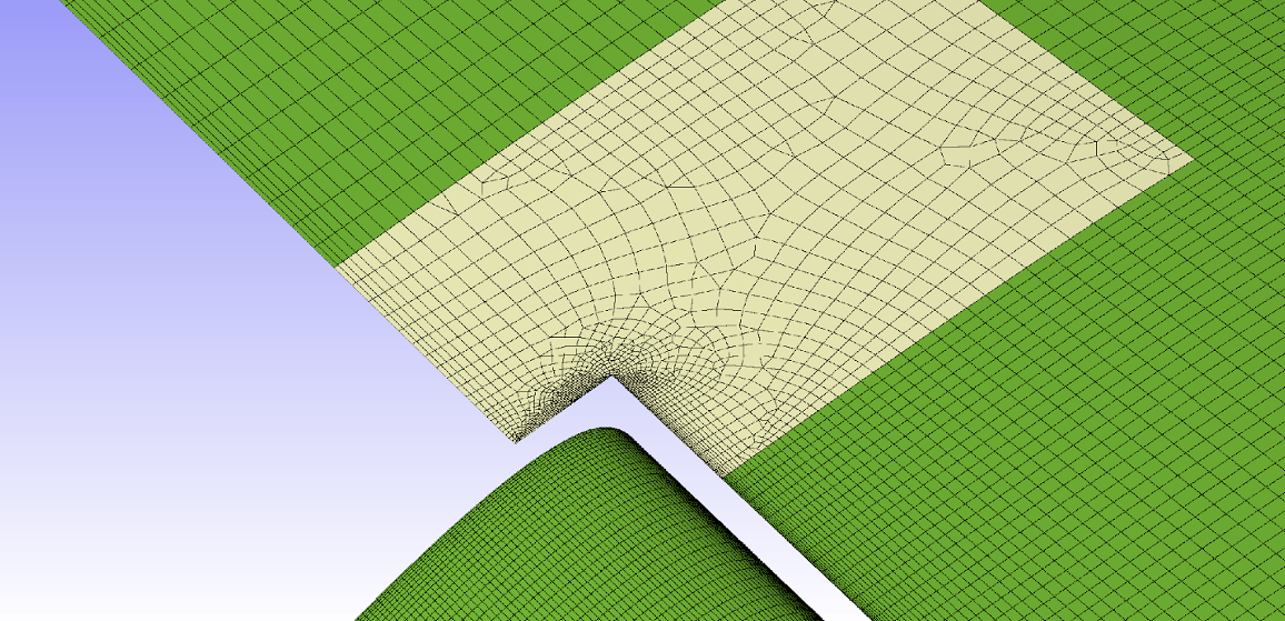
Figure 3 – Structured mesh and quad-dominant mesh transition.
After that, the volume mesh is generated by extruding the surface mesh. The T-Rex feature in 3D of Pointwise is used here for high-quality boundary layer mesh. A Glyph script is employed to generate volume mesh automatically with parametric control of source cell sizes, first layer height, growth rate, and many other parameters. The script allows the user to keep full control of the mesh quality so that a smooth transition between the boundary layer and the outer domain cells is designed. A smooth transition ensures a proper capture of the boundary layer velocity gradients and prevents the raise of numerical instabilities. The cutting sections of the volume mesh of both take off and cruise wing shapes are shown in Figure 4. The transition of blue hexahedra cells to yellow pyramid cells and finally to red tetrahedra cells can be clearly seen. The green cells are prisms and they may appear in correspondence of triangular surface cells.
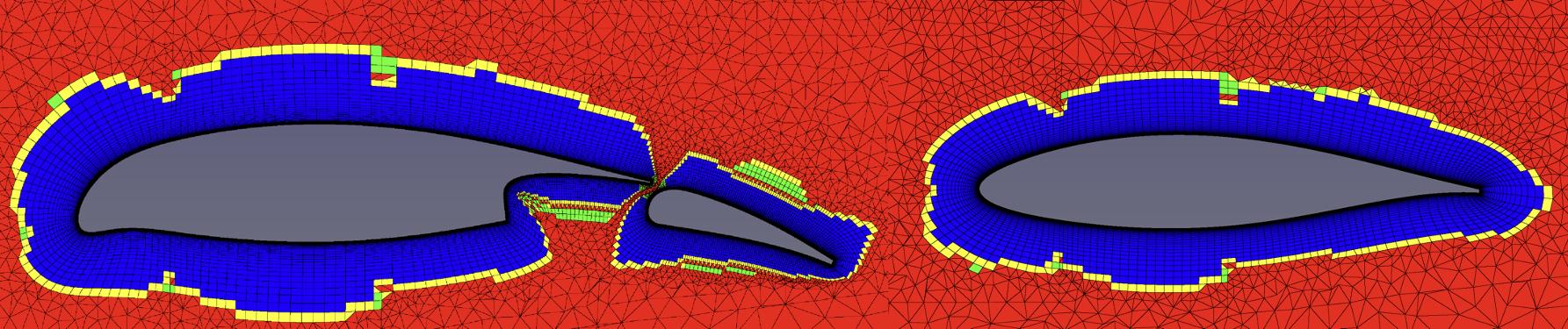
Figure 4 – Volume mesh cutting section for take off (left) and cruise (right) wing shapes.
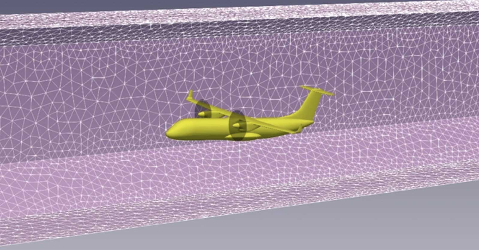
To compare the CFD results with the wind tunnel experimental results, the influence of the wind tunnel walls should be accounted for. Hence, a setup with wind tunnel-shaped domain walls is also studied to compare with the free stream case. Then the influence of the wind tunnel walls can be quantified to calibrate the experimental results to have a more reasonable comparison with the free stream CFD results. To generate the mesh for different AoAs, the near-field extruded mesh is kept fixed and only the far field is remeshed. The procedure has been automatized by means of Pointwise Glyph2 scripting. This has also reduced the turn-around time for generating all wind-tunnel meshes for different AoAs.
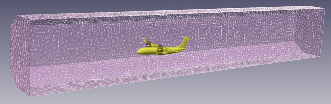
Figure 5 – CFD model enclosed by wind-tunnel walls.
For the CFD simulation, M-Edge general-purpose finite volume flow solver is used which is able to handle hybrid meshes, i.e. a combination of structured and unstructured grids. Steady-state Reynolds averaged Navier-Stokes (RANS) are solved with two combined turbulence models. The Wallin & Johansson explicit algebraic Reynolds-stress model (EARSM) together with the Hellsten k- two-equation model are used, as they are known to capture some effects of strong three-dimensionality such as swirl and corner flow separation, e.g., related to wing-body and wing-pylon interactions [2-3]. Thanks to the meshing capabilities of Pointwise, the free stream CFD results show a good match with the corrected wind tunnel experiment results, especially in the linear regime of AoAs (10 to 15 degrees).
The CFD results of the actuator disk model and the whole aircraft are shown in Figure 5. The results from the separate actuator disk model are used to calibrate the data used in the whole aircraft such as blade pitch angle. The downstream flow behavior of the propeller and the interactions with the wing can be clearly observed as well as the asymmetry induced by the co-rotating propellers.
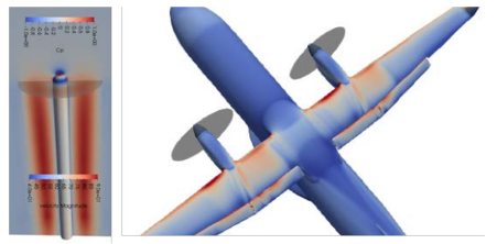
Figure 6 – Illustration of the calibration of the propeller actuator disk model. Isolated propeller in free flight (left) and installed on the aircraft model (right).
[1] S. Wallin, A. Hanifi, S. Adden, F. Amoroso, and F. Bagheri, “Novel Morphing High-Lift Devices for Laminar Wing Design of Turboprop Aircraft – Large-Scale Wind-Tunnel and CFD Assessment,” presented at the 9ᵀᴴ EUROPEAN CONFERENCE FOR AERONAUTICS AND SPACE SCIENCES (EUCASS), 2022.
[2] A. Hellsten, “New advanced k-ω turbulence model for high-lift aerodynamics,” AIAA journal, vol. 43, no. 9, pp. 1857-1869, 2005, doi: 10.2514/1.13754.
[3] S. Wallin and A. V. Johansson, “An explicit algebraic Reynolds stress model for incompressible and compressible turbulent flows,” Journal of fluid mechanics, vol. 403, pp. 89-132, 2000, doi: 10.1017/S0022112099007004.
Category
Aerospace
Application
Morphing High Lift devices
Date
November 2022
Project Partner
KTH - Recycle EU project
Pointwise Key Features
2D TRex around sharp corners, 3D TRex for volume mesh, Glyph scripting for varying far-field domain and Multi-block 3D mesh