
Structured Mesh of an Axial Turbine Rotor Blade
CFD can facilitate the design of turbomachinery to optimize its efficiency, which is very important as the industry is putting more and more focus on sustainability. An optimized and accurate CFD simulation workflow can save a lot of time and money for a company’s research and development. And a high-quality mesh is a key prerequisite to accurate CFD results.
In this case study, we will investigate a multi-block structured mesh of a single axial rotor blade generated with Fidelity Pointwise. The geometry surfaces contain the rotor surface, hub, shroud, and one periodic boundary surface.
This case is one example of the tutorial workbook given in the software. The detailed step-by-step tutorial on how to set up the mesh can be found in Chapter 11: Axial Turbine Blade of Pointwise tutorial workbook.
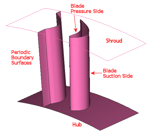 Figure 1. The geometry of the axial rotor case
To create a high-quality structured mesh for this rather complex geometry, we need to divide the domain into several blocks. First, it is a good idea to generate a boundary layer block around the blade to capture the viscous effect close to the wall. The boundary layer block is shown in Figure 2. Note that the areas close to the leading edge and trailing edge as well as the hub and shroud have denser mesh, as these places usually have high velocity gradients and more complex flows.
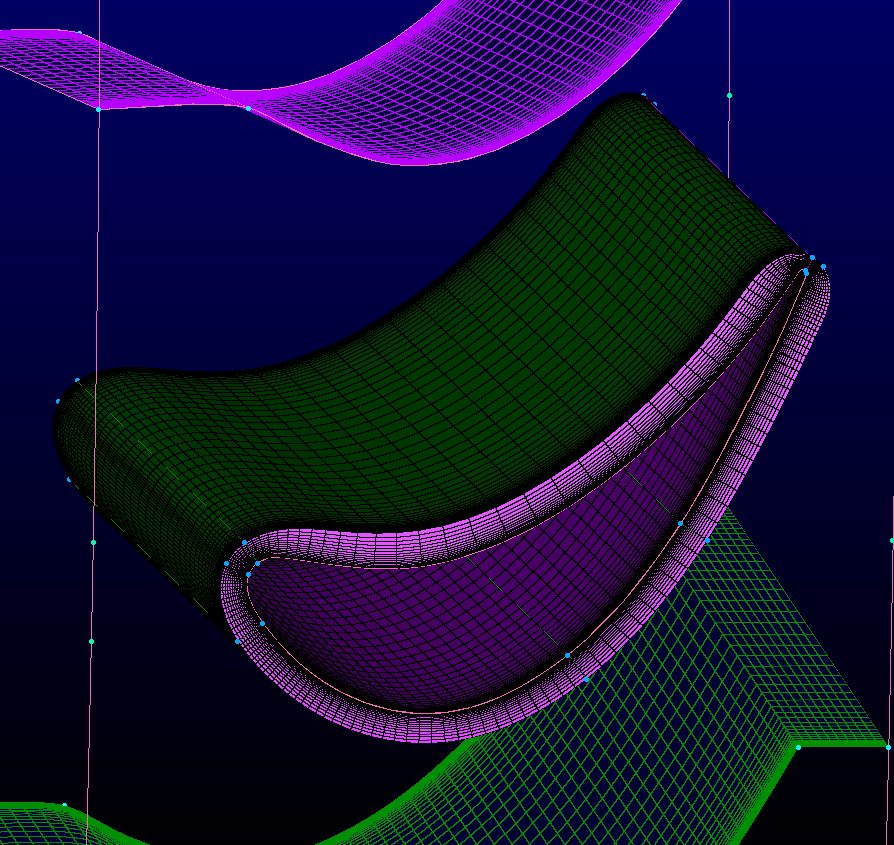
Figure 2. Boundary layer block around the blade
Next, we must define the topology of the space. To ensure a high-quality structured mesh around the blade, we need to divide the domain into several sub-domains. Figure 3 illustrates one example. The 1D connectors are created such that 7 different sub-domains are formed. The distributions of the points in the connectors are also adjusted to ensure a smooth transition and different densities at different places. For example, the mesh is denser around the leading edge and trailing edge of the blades to capture the more complex flow characteristics there.
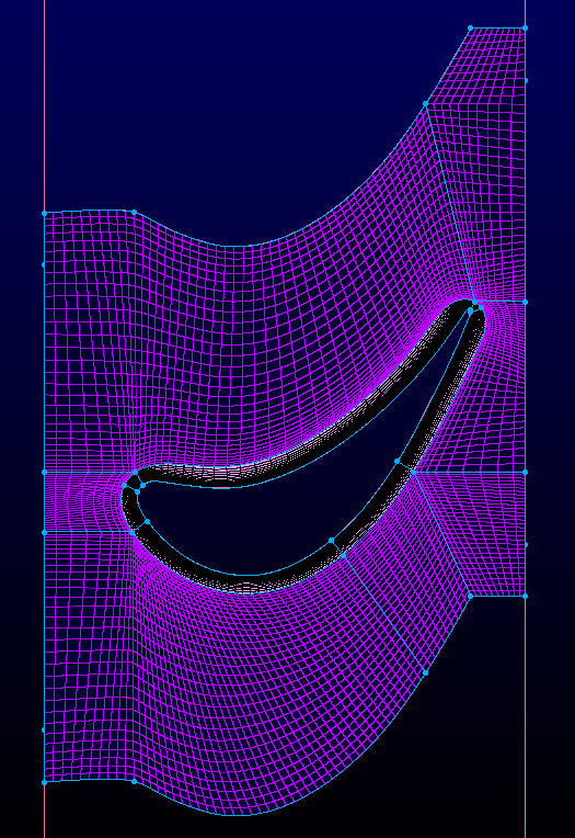
Figure 3. Topology of the structured mesh
At this stage, we’ve essentially completed the 2D mesh. However, there are ways to improve the transition of the cells further. In Pointwise, there is this unique elliptic solver which can further smooth the orthogonality and spacing at the boundaries of domains. Select all the hub and shroud domains and click “Grid-Solve”, then go to “Edge Attribute” panel. The settings are shown in Figure 4. Two types of boundary control functions are available to choose from, the Steger-Sorenson function and the von Lavante-Hilgonstock-White function. The latter will enforce orthogonality and spacing at the boundaries exactly as the given constraints and can sometimes deteriorate the cell quality. So, in this application, we opt for the former function, which only maintains the constraints approximately and puts more focus on the smoothness of the cells. The boundary condition is selected as “Floating” which will allow the connectors shared by multiple domains to change shape. The result after 50 iterations is shown in Figure 5.
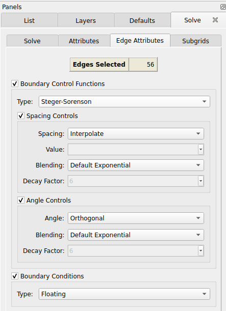
Figure 4. Settings for the elliptic smoothing applied on the hub and shroud domains
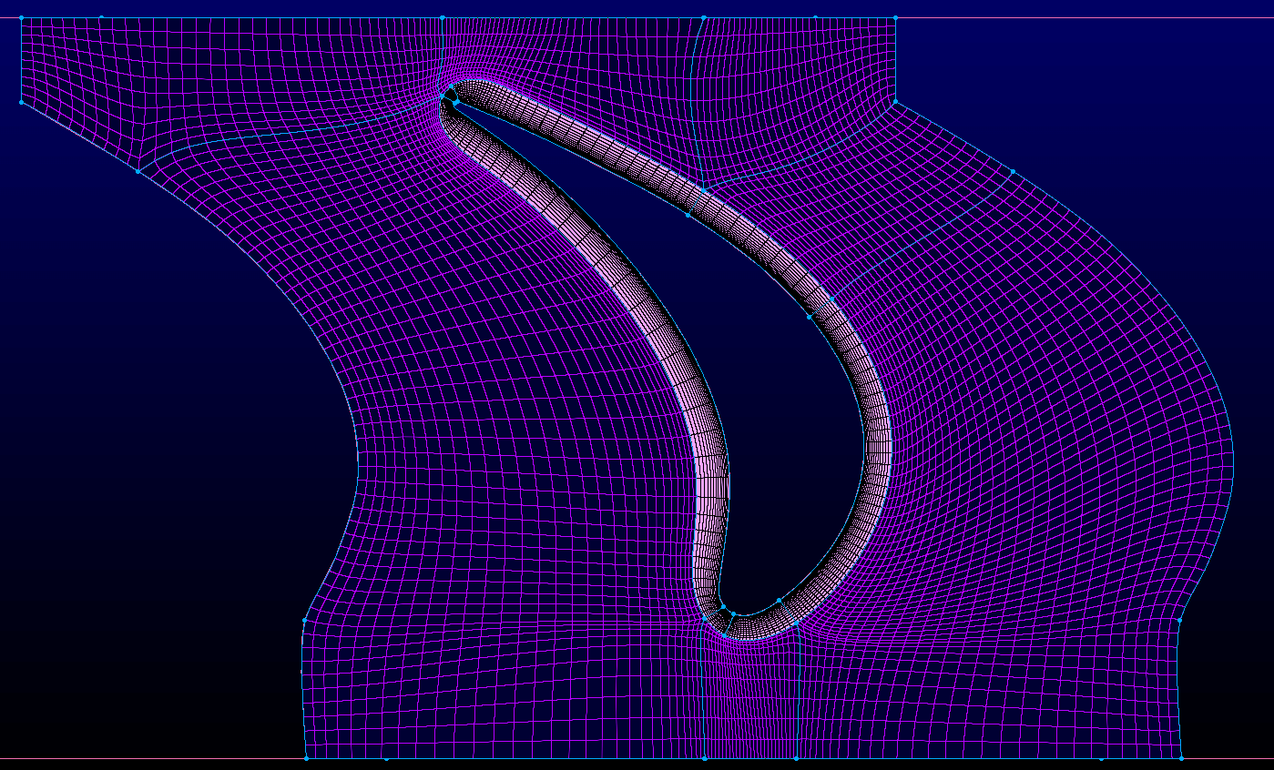
Figure 5. Mesh after elliptic smoothing
To examine the quality of the mesh, the Minimum Included Angle can be used to check the skewness of the cells. In principle, highly skewed elements should be avoided. The shroud and hub domains are of more interest here. The results of the hub domain are shown in Figure 6. The quality has already been improved a lot with the help of the elliptic solver which smoothens the connectors. But as we zoom in to the minimum value, we can see some highly skewed cells near the trailing edge due to the nature of the topology as shown in Figure 7.
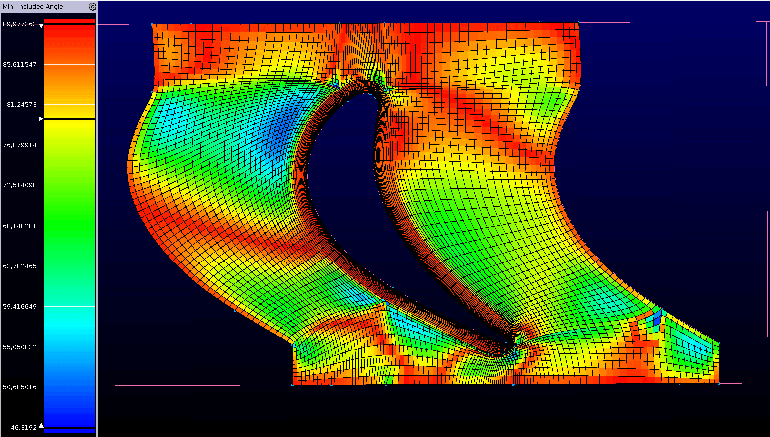
Figure 6. Minimum Included Angle of the hub domains
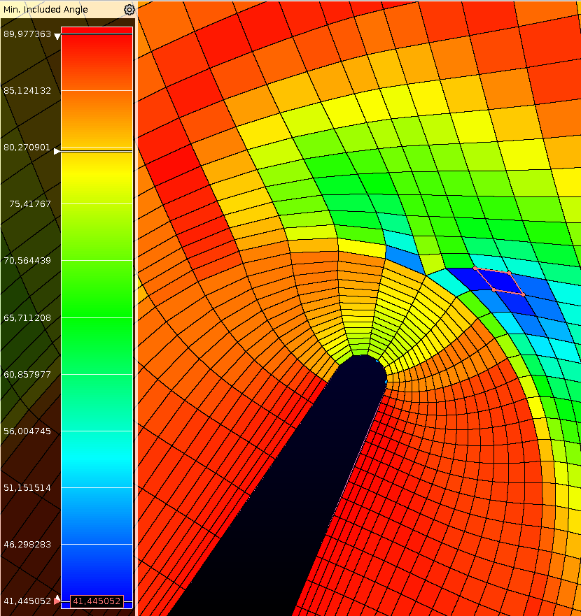
Figure 7. Zoomed-in view of the minimum value near the trailing edge
These specific cells can be further improved by manually tweaking the curve of the connectors at the trailing edge, as shown in Figure 8. The orthogonality of the cells can be improved by making the slope of the connector more orthogonal to the domain boundaries. The improved cells are displayed in Figure 9. This feature showcases again that the user has full control of the mesh in Pointwise.
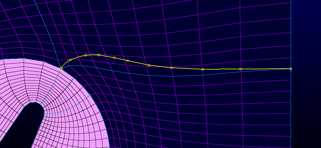
Figure 8. Edit the shape of the connector
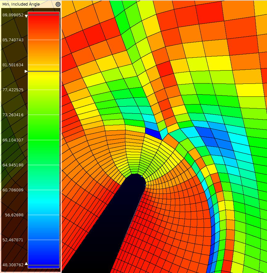
Figure 9. Improved cell quality near the trailing edge
A structured mesh is generated around a turbine blade in this case study. And Pointwise demonstrated its powerful and useful features and the ultimate control that is given to its users over various mesh parameters. This makes Pointwise a very versatile choice for engineers who pursue the best mesh quality in the way they want.
Category
Turbomachinery
Application
Axial Turbine Blade
Date
March 2024
Project Partner
-
Pointwise Key Features
Multi-block structured grid, Boundary control functions for elliptic smoothing, Connectors shape manual adjustment, Cell quality examination